
Max Simmonds
M.Eng (Hons) First Class
Software engineer at Starship Technologies and co-founder of Purple Parrot. Previously at CERN and ESA. MEng (Hons, 1st) from the University of Plymouth. Based in Tallinn, Estonia.
Project Status
Robot Dog Butler
28/02/26
Project started today!
05/05/26
Today’s the day I actually start this! It’s been 3 months since I promised my daughter we would make a robot dog. There’s been a few things that have stopped me:
- They’re expensive
- They take a lot of time commitment
- I don’t have a good solution for the BLDC driver, which ties into point 1.
But, last night, I was using Claude to review a previous BLDC motor design of mine and I realised how awesome (although, I already knew, just didn’t think about it for this implementation) it is for asking questions like “how do I size the DC link capacitors” and “why did this latch up my MCU when going down hill and regenerating”.
It did a really good job explaining the physics, which was the intuition I was missing. How much energy a hill is generating:
\[E = P \cdot t = \tau \cdot \omega \cdot t\]This was close to 500w of mechanical power into the system, and that has to go somewhere. Anyway, I digress. The point is, we started talking about FOC (Field Oriented Control) which is a requirement for the BLDC driver in this project. I was initially worried about this, but, as Claude showed me, I know most of the math already: Clarke Transform, P/Q transform, then two controllers (PI). It’s been a few years since I’ve done those, but It’ll be fine.
Anyway, to that end, I thought a cool way to start would be:
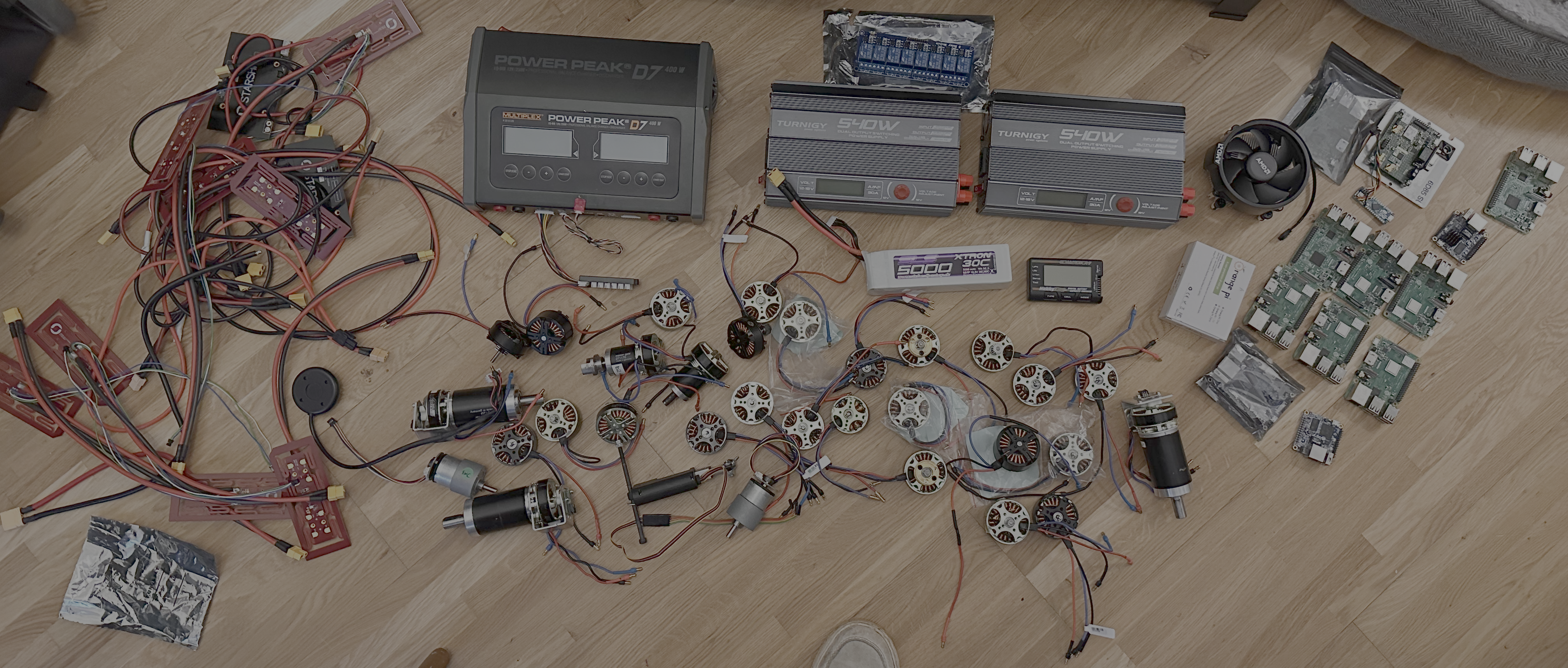
- Look through my collection (see above) of motors, find the highest torque one
- Find a design of a leg online -> 3D print to match my chosen motor
- Either buy an odrive or Chinese replica, and see if I can get this leg to jump. Will be used initially for a torque test/firmware control
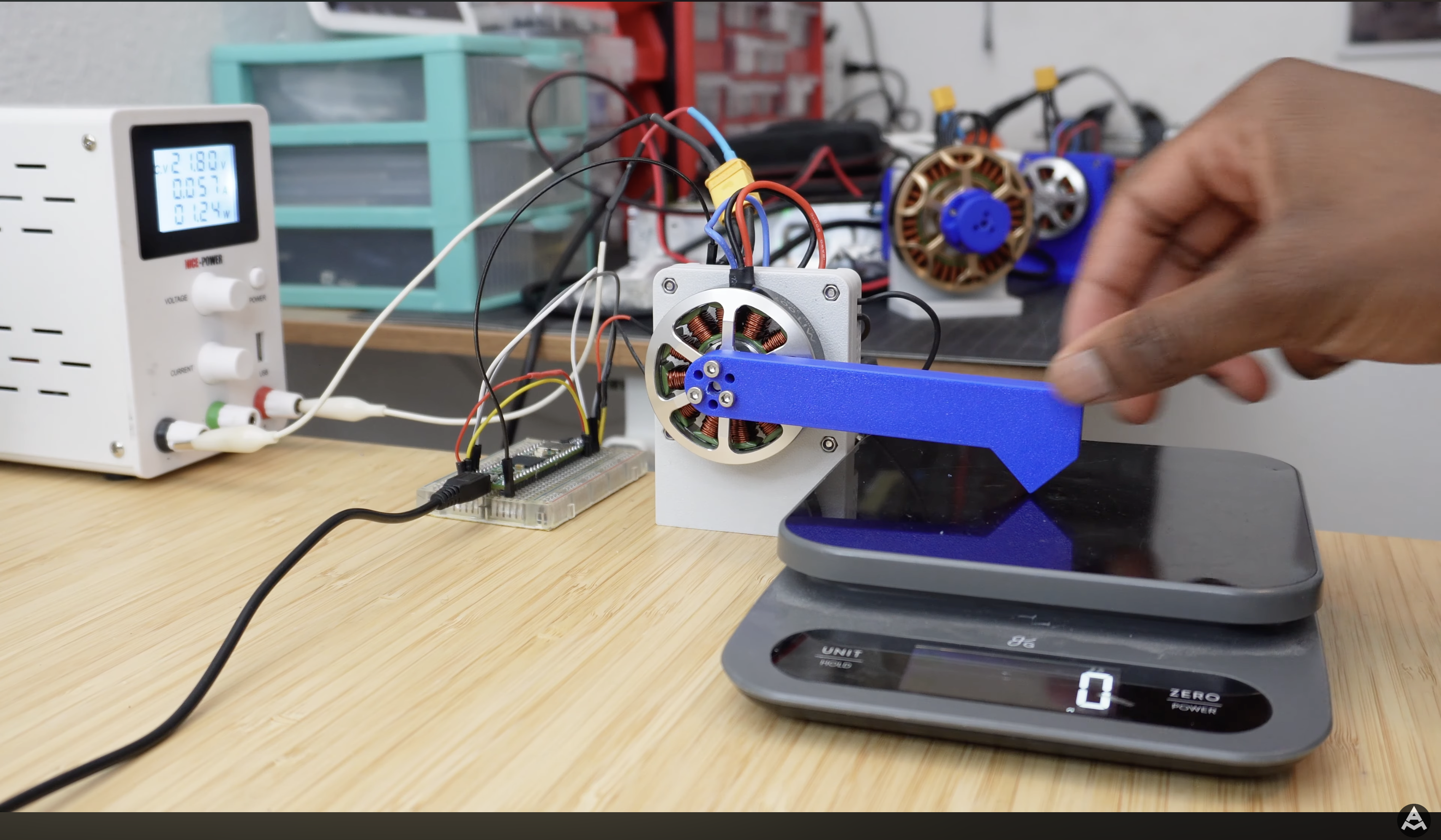
This is the setup used by Aaed Musa who’s built a couple of dog bots now, I believe James Bruton does something similar, too.
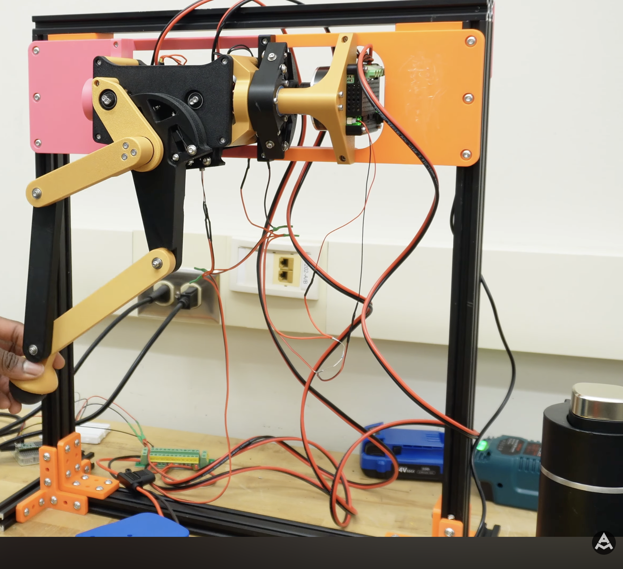
The test jig I envision to look like the above. I don’t currently have any Al extrusion, but if I get that far, I’ll buy some.
What I Want To Get From This Project
Before I get too into the weeds on this, I thought it would be a good idea to quantify what I would like to learn from this project. That way, when it’s done, I can look back and see how far I’ve come.
- FOC - field orientated control
- More about robots, I see my career and engineering moving towards physical AI, having a good foundation on modern robots will help
- Quasi direct drive actuators
- A more intuitive understanding of electric motors
- Control loops for “springy” legs
- Fast prototyping with 3D printing (I have a good background in 3D printing, but not so much with fast iterative designs)
There’s probably a bunch more, but those are the ones I can think of right now. Time to find a leg to print!
07/05/26
I’ve been wanting to build a test leg for a while. As I mentioned, I got a bunch of motors from my workplace, so I rummaged through the box and found 3 (two of which are basically the same from different manufacturers).
- Turnigy Multistar 4822-390Kv 22Pole Multi-Rotor Outrunner (the other is basically the same as this, not branded)
- A generic X4114-370 24 poles (I think)
I have a bunch of things I want to do regarding this motor controller design:
- Understand the motor itself, how it works, why Field Oriented Control is desirable
- How does BEMF manifest itself, how and why does it occur?
- Model of a 3 phase full bridge driver - for testing different control strategies, starting with trapezoidal, moving on to FOC.
- Model of a motor, maybe not the full dynamics but at least an RL (C?) with BEMF
- Fortesque transform, it’s derivation, intuition, and application in FOC
- Clarke / P and Q transform, it’s derivation, intuition, and application in FOC
- Characterisation of bearing eccentricity and it’s affects on motor control (this is a bit of a stretch goal if I have time, I can’t imagine it’s going to be of paramount importance).
Not sure how I will blog this, probably different projects, all linked here or something.
Anyway, this latest update is is about how I disassembled the x4114. This has the best torque capabilities out of all the motors I currently have, and I have two of them (only! I have about 30 of the others). That’s enough to make a test leg, measure torque, learn a bunch and get a feel for how much torque I need in practice.
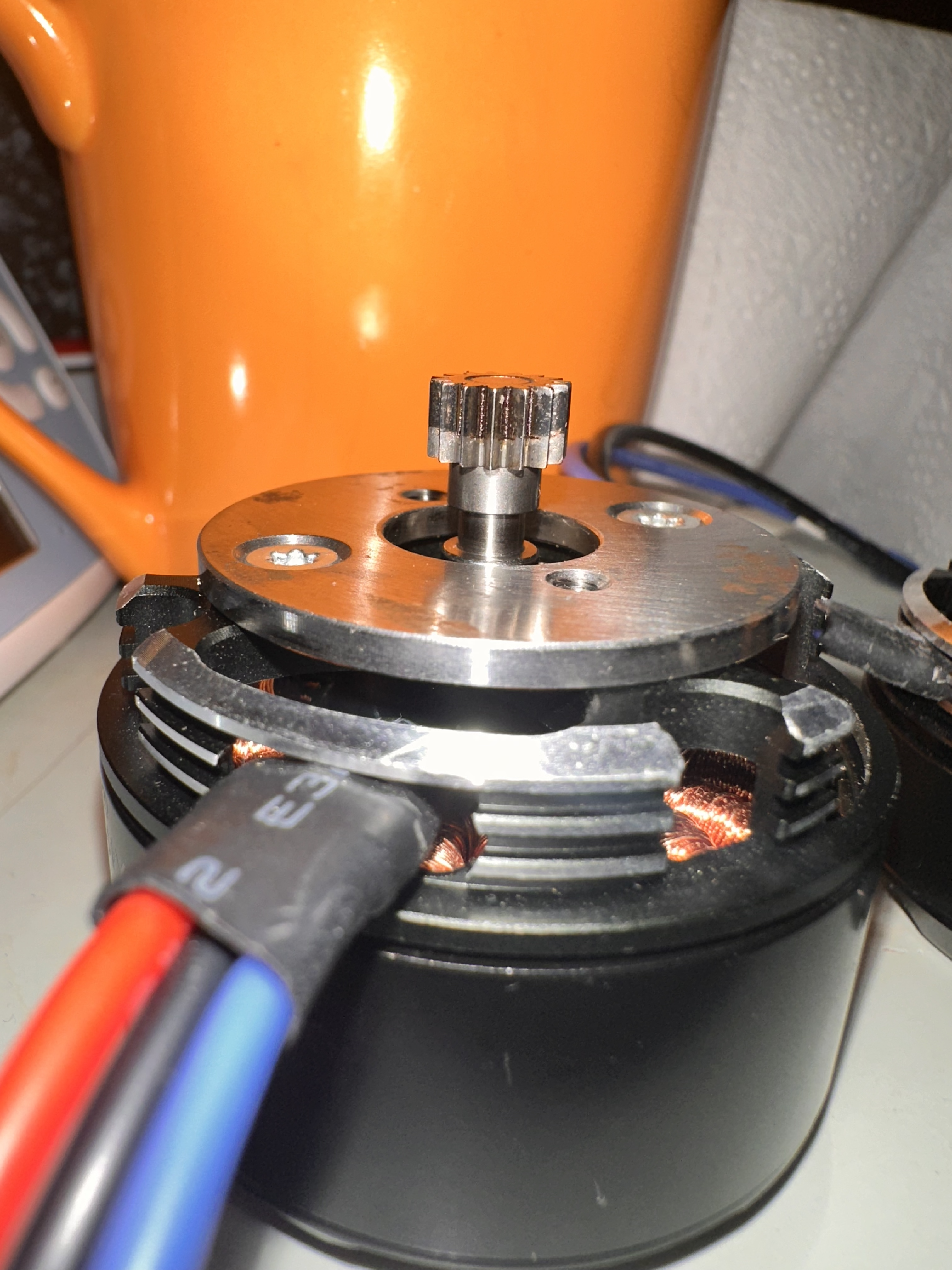
Above shows the image of the motor. The current issue is, I don’t need that spur gear. I’ve been looking at the cycloidal drive (which will be yet another project, linked here no doubt) and I will be printing my own spur gear, much larger in diameter. So, this has to go! Long story short, it was not as easy as I thought. I tried twisting it off in the vice, using dowels to hammer it out, a hot air gun at 200 Deg C, levering with screwdrivers, the lot. I got these second hand from work, so I checked the intranet to see if they had documented how they added the gear, and luckily they did! Not for this exact motor, but one very similar. It was, of course, push fitted via a press and loctite’d into place.
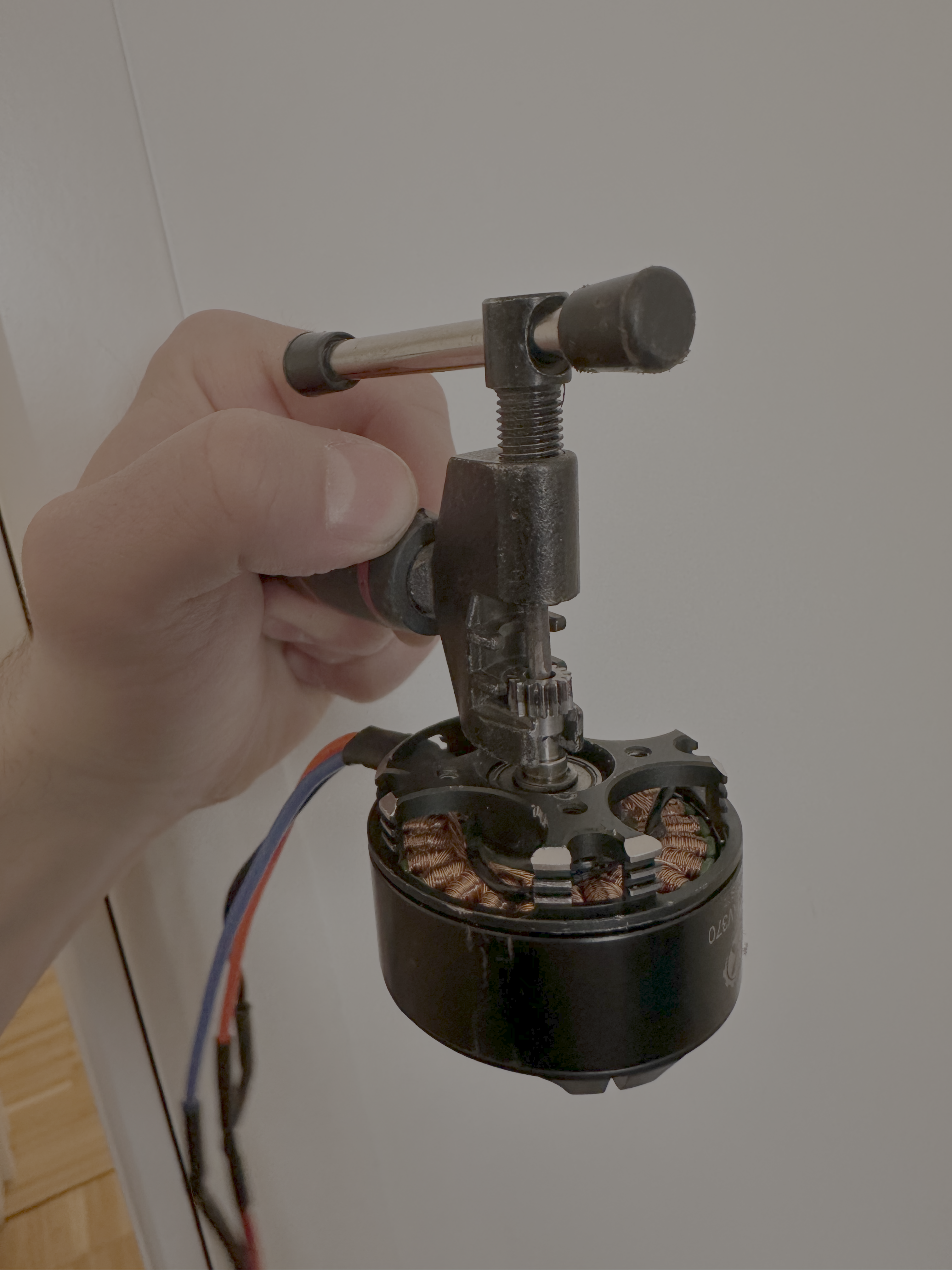


I managed to come up with a pretty novel solution; using an old bicycle chain splitter (that I bought 9 years ago in the Netherlands!). With a slight modification with a Dremel I was able to make a poor mans gear puller!
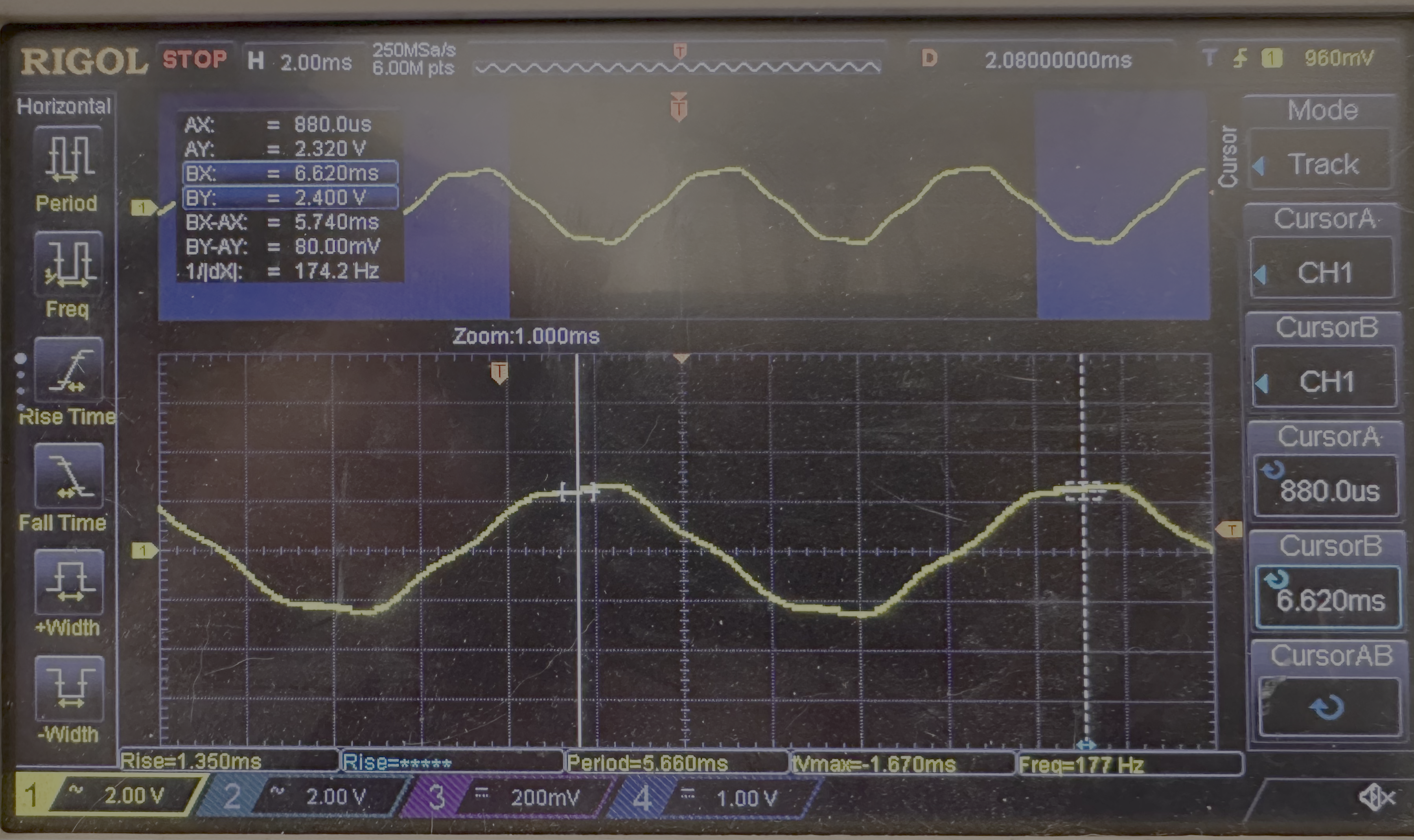
Lastly, I used my hand held drill to spin up the motor, and measure the voltage across two of the phases. This was in an attempt to measure the KV - motor velocity constant - measured in RPM/V. IE, how many revolutions per minute, per volt, is generated by the motor. It’s often called the BEMF constant, too.
This is where, I think, things get a little complicated. There’s 2 types of rotation going on here. We have the mechanical frequency, the number of rotations of the bell/outer case per second, and the electrical rotation, which is one full electrical cycle, a N-S-N change across a stator tooth. That means for one mechanical rotation, there are \(f_{mech} = p \cdot f_{elec}\) where p = number of poles. Our current motor has 22 magnets, and 24 teeth (known as poles and slots, respectively). Therefore, the we can determine the KV of the motor with the following:
\[KV = \frac{\text{electrical RPM}}{V_{phase peak}}\]I’ve left out the “fudge factor” at the moment. There’s a constant that’s added to the denominator. This is a result of three things, but the one I understand intuitively at the moment, and makes the largest contribution to this motor, is the ‘spread’ of the vector across the stator teeth. Motors are often |nd such that neighbouring slots are of the same phase, but opposite polarity (make sense, you need an N/S pair - often stators also have the opposite slot (180 deg) be the opposite, too). Anyway, if you do the math, then 8 vectors pointing ~15 deg apart, 4 on one side and 4 on the other, gives you an overall vector pointing ~0.95x what a vector pointing perfectly straight would. That’s the fudge factor that’s sometimes added.
\[KV = \frac{\frac{177}{11}*60}{2.4} \approx 400\]Pretty close to the stated 370 KV.
13/05/26
I’ve been spending some time looking through various cycloidal drives, trying to understand how they work. As well as that, I was deep diving into how BLDC motors work, how field orientated control works, Fortesque transforms, Clarke transforms, etc. There’s a lot to learn and I don’t have much time, but I think it’s important to get a good grasp on these concepts, as they come up over and over and over in other areas.
Anyway, I’m not in a place to update about that yet, but I can with the cycloidal drive.
Here’s were I am so far. I settled on taking James Bruton’s v3 cycloidal drive. Mainly, it was simple enough to quickly understand what I needed to print, and a pretty similar motor to what I had. I scaled the design down based on the ratio of motor diameters, I needed to make it almost half the size.
There’s a bunch of things that need to be changed, which is why I’m writing this update, I want to formalise them so I can understand what I need.
- The screw holes didn’t scale down well. They ended up being 1mm or something. Smallest screws I have are M2s, I’ll redo the designs to account for this.
- The cover isn’t the right size, needs to be redesigned.
- The cycloidal gears might need to be made smaller ever so slightly, they pinch a bit. This might be because the roller bearings that sit on the outside of the cycloidal gears aren’t well dimensioned, 3D printing small tubes is never great. I can either make these part of the body of the gear, I don’t think they really need to roll, or, replace with Teflon tubes that I buy.
- The eccentric gear needs some consideration, it’s very thing, I thin it’ll snap pretty quickly. I reckon I can make it thicker, and maybe change how the two are connected.
- Need a better solution for the small bearings and spacers - in fact, all bearings need some thought. If I do use metal bearings (and probably I will need too) then they need to be a standard size, so I’ll need to account that.
23/05/26
Okay, it’s been a while since I posted, but I’ve actually been working a lot on this. I’d be splitting my efforts between designing the cycloidal drive, arguably the most important part of the dog bot, and understand how BLDC outrunners work. Specifically, I’ve been looking at:
- What causes the motor to turn?
- What are the stator winding patterns?
- Why do they have seemingly random pole / slot ratios? (22/24, for example)
- Trapezoidal vs Field Oriented Control
- Fortesque and Clarke / PQ transforms
- Forces on conductors in magnetic fields
- Lorentz forces
- Back EMF (BEMF) and modelling this in LTSpice
Cycloidal Gearbox Development
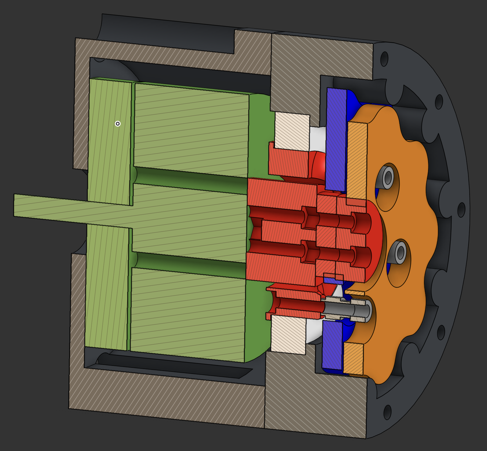


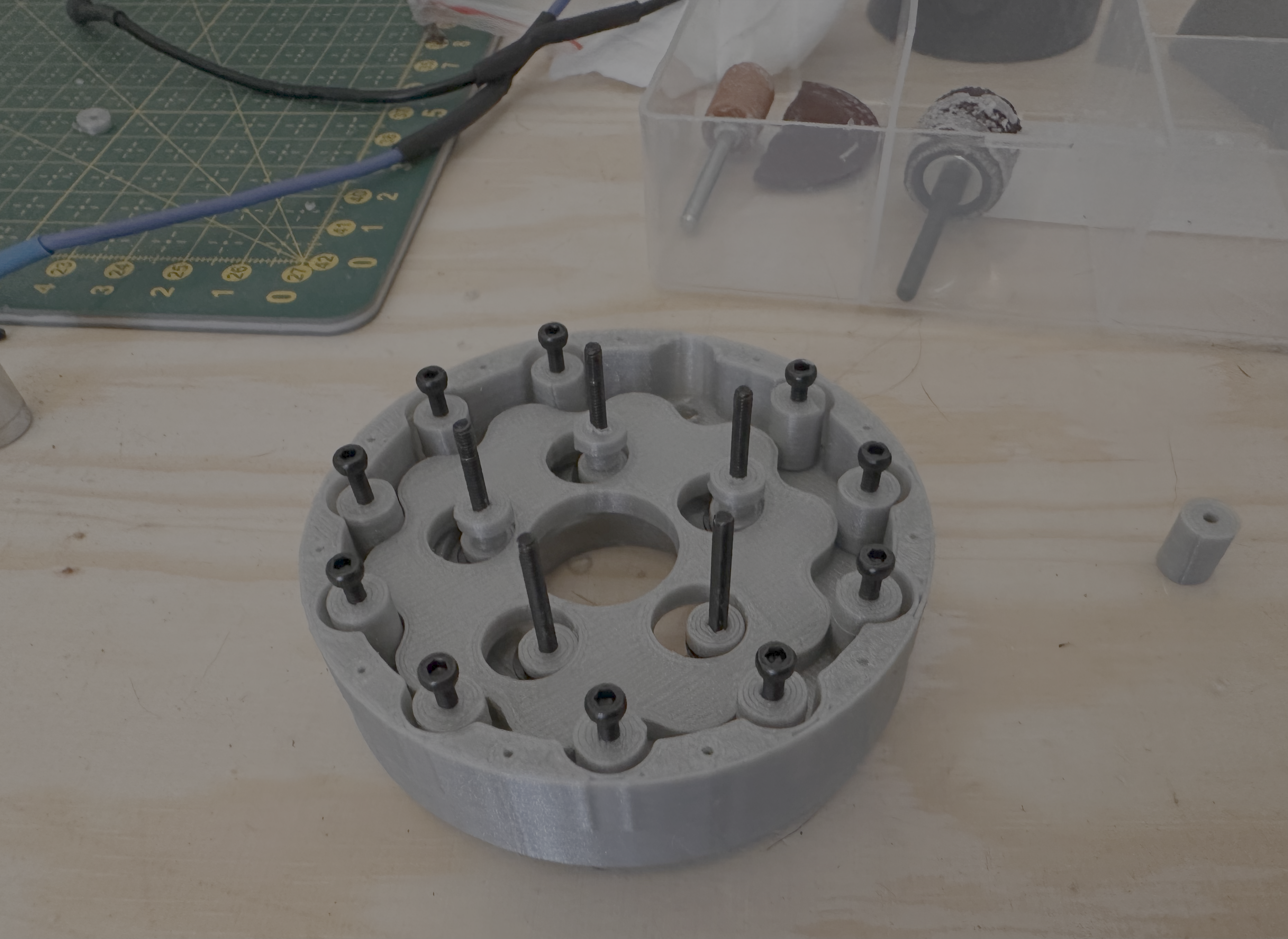
Gearbox development is going well. I have printed these components now, and tested using a drill, all seems to be working!
The outstanding parts are the top output drive cup (? can’t think of a better name!) and the plate that caps the gear ring holder (again, no idea what’s a good name for that). I need to make a few mods to the current design, just for “assembability”, but I’m happy with the progress!
BLDCs - How They Work?
Let’s start off with the physics at play in BLDCs, before we jump into stator windings, poles, slots, etc.
It all starts with how a force is generated, and that comes from:
\[F = IL \cross B\]That is, the force